oder so!
[9000] ECU fault codes and how to read them.
Contributed by Andrew
A guide to pulling fault codes for all models of electronically fuel injected Saabs to 1998. The guide also has a list of fault codes and their meaning. Guide is broken down by type of ECU/Fuel Injection.
Contents
Index of vehicles
Self-Diagnosis
Introduction
Self-Diagnosis connector location
Retrieving fault codes without a fault code reader (FCR) - flash codes
Clearing fault codes without a fault code reader (FCR)
Actuator testing without a fault code reader (FCR) - Bosch LH2.4 only
Self-Diagnosis with a fault code reader (FCR)
Guide to test procedures
Fault code tables
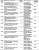
Index of vehicles
Model Engine code Year System
900i 16V DOHC B202i 1989 to 1990 Lucas 14CU LH-Jetronic
900 Turbo 16V DOHC B202 2S 1988 to 1990 Lucas 14CU LH-Jetronic
900 2.0 16V DOHC cat B202 2L 1989 to 1993 Lucas 14CU LH1-Jetronic
900i 16V DOHC cat B202i 1990 to 1993 Lucas 14CU LH-Jetronic
900S Turbo cat B202i 1990 to 1993 Lucas 1 4CU LH-Jetronic
900 2.Oi 16V DOHC B202i 1993 to 1997 Bosch Motronic 2.10.2
900 Turbo 16V DOHC B202i 1994 to 1997 Saab Trionic
900i 16V DOHC B206i 1994 to 1997 Bosch Motronic 2.10.2
900i 1 6V DOHC B204L 1994 to 1997 Bosch Motronic 2.10.2
900 2.3i 16V DOHC B234i 1993 to 1997 Bosch Motronic 2.10.2
900 2.5i 24V DOHC B258i 1993 to 1997 Bosch Motronic 2.8.1
9000i 1 6V cat B202i 1988 to 1993 Bosch LH2.4-Jetronic
9000 and CD16 B202 1991 to 1993 Bosch LH2.4.2-Jetronic
9000 16V cat B202 1988 to 1993 Bosch LH2.4-Jetronic
9000 Turbo 16 B202 1991 to 1993 Bosch LH2.4.2-Jetronic
9000 Turbo 16 cat B202 1989 to 1993 Bosch LH2.4-Jetronic
9000 2.Oi cat B204i 1994 to 1997 Saab Trionic
9000 2.0 Turbo cat B204S 1994 to 1997 Saab Trionic
9000 2.0 Ecopower B202S 1992 to 1993 Bosch LH2.4-Jetronic
9000 2.0 Turbo Intercooler B204L 1994 to 1997 Saab Trionic
9000i 2.3 cat B234i 1990 to 1991 Bosch LH2.4.1-Jetronic
9000i 2.3 cat B234i 1991 to 1993 Bosch LH2.4.2-Jetronic
9000 2.3i cat B234i 1994 to 1997 Saab Trionic
9000 2.3 Turbo cat B234L 1994 to 1997 Saab Trionic
9000 2.3 Turbo cat B234R 1994 to 1997 Saab Trionic
9000 2.3 Turbo cat B234R 1993 Saab Trionic
9000 2.3 Turbo cat B234L 1991 to 1993 Bosch LH2.4-Jetronic/Saab Direct Ignition
9000 2.3 Ecopower LIP Turbo B234E 1994 to 1997 Saab Trionic
9000 3.0 24V DOHC B308i 1995 to 1997 Bosch Motronic 2.8t
Self-Diagnosis
Introduction
The engine management systems fitted to Saab vehicles are Lucas 14CU, Bosch 2.8.1 and 2.10.2, Saab Trionic and Saab Direct Ignition (with Bosch LH 2.4.1 and 2.4.2 fuel injection). Bosch Motronic controls fuel Injection, ignition and idle functions from within he same control module. Saab Trionic controls the ignition, fuel injection, idle and turbo boost pressure. Saab Direct Injection controls ignition and Turbo boost alone. Lucas 14CU and Bosch LH fuel injection systems control fuel injection and idle functions alone.
Self-Diagnosis (SD) function
Each ECM (electronic control module) has a self-test capability that continually examines the signals from certain engine sensors and actuators, and then compares each signal to a table of programmed values. If the diagnostic software determines that a fault is present, the ECM stores one or more fault codes in the ECM memory. Codes will not be stored about components for which a code is not available, or for conditions not covered by the diagnostic software. Saab models generate either 2- or 5-digit fault codes, which may be retrieved either by fault code reader (all systems) or by manual means as flash codes (all except Saab Trionic and Saab Direct Ignition).
Limited operating strategy (LOS)
Saab systems featured in this Chapter utilise LOS (a function that is commonly called the “limp-home mode”). Once certain faults have been identified (not all faults will initiate LOS), the ECM will implement LOS and refer to a programmed default value rather than the sensor signal. This enables the vehicle to be safely driven to a workshop/garage for repair or testing. Once the fault has cleared, the ECM will revert to normal operation.
Adaptive or learning capability
Saab systems also utilise an adaptive function that will modify the basic programmed values for most effective operation during normal running, and with due regard to engine wear.
Self-Diagnosis (SD) warning light
Saab models are equipped with an SD (Check Engine) warning light located within the instrument panel. Some fault conditions will illuminate the light during normal engine operation, and the ECM will need to be interrogated to determine if fault codes are indeed stored in ECM fault memory.
Self-Diagnosis connector location
Bosch Motronic and Saab Trionic
The 16-pin SD connector for FCR use and manual code retrieval is located either under the facia on the driver’s side above the foot pedals (see illustration 29.1) or under the passenger’s seat.
Lucas I4CU
The 3-pin SD connector is for FCR use and manual code retrieval, and is located in the engine compartment, adjacent to the heater air intake.
Bosch LH2.4, 2.4.1,2.4.2
The SD connector for FCR use and manual code retrieval is situated in one of the following locations: under the rear seat, in the engine compartment, or in front of the gear selector.
Saab Trionic and Saab Direct Ignition
The SD connector is black, and is located close to the ECM under the right-hand front seat.
Retrieving fault codes
without a fault code reader (FCR) - flash codes
Note: During the course of certain test procedures, it is possible for additional fault codes to be generated.
Care must be taken that any codes generated during test routines do not mislead diagnosis. All codes must be cleared once testing is complete.
Lucas I4CU
I Attach an accessory switch between the SD connector and earth (see illustration 29.2).
2 Switch on the ignition and the SD warning light will illuminate.
3 Immediately close the accessory switch. The SD warning light will extinguish and then illuminate for one short flash.
4 Immediately open the accessory switch.
5 The SD warning light will display the 5-digit fault codes as follows:
a) The five digits are indicated by five series of flashes.
b) The first series of flashes indicates the first digit, the second series of flashes indicates the second digit, and so on until all five digits have been flashed.
c) Each series consists of a number of flashes separated by short pauses. Each integer (whole number) in the range 1 to 9 is represented by a number of short flashes, and each zero is represented by a longer flash.
d) A pause separates each series of flashes.
e) The code number “12232” is indicated by a flash, a short pause, two flashes, a short pause, two flashes, a short pause, three flashes, a short pause and two flashes. A long flash is displayed at the beginning and end of each code.
6 Count the number of flashes in each series, and record each code as it is transmitted. Refer to the tables at the end of the Chapter to determine the meaning of the fault code.
7 To retrieve the next code, close the accessory switch and wait for the SD warning light to flash once.
8 Immediately open the accessory switch, and the SD warning light will display the next 5-digit fault code.
9 Repeat the procedure until all fault codes have been retrieved.
10 If a return to the first code is required, close the accessory switch and wait for the SD warning light to flash twice, then immediately open the accessory switch. The first code will be transmitted again.
11 Five long flashes indicates that all the fault codes have been retrieved, or that no codes are stored.
12 Turn off the ignition and remove the accessory switch to end fault code retrieval.
Bosch LH 2.4, 2.4.1, 2.4.2
13 Attach an accessory switch between the SD connector and earth (see illustrations 29.2 to 29.4).
14 Switch on the ignition, and the SD warning light will illuminate and then extinguish.
15 Close the accessory switch. The SD warning light will illuminate for one short flash.
16 Immediately open the accessory switch.
17 The SD warning light will display the 5-digit fault codes in the same way as described for the Lucas 14CU system (see paragraphs 5 to 12).
Bosch Motronic 2.8.1 and 2.10.2
18 Attach an accessory switch between pin 6 of the 16-pin SD connector and earth.
19 Switch on the ignition.
20 Close the accessory switch for between 1 and 4 seconds.
21 Open the switch, the SD warning light will now illuminate for 2.5 seconds, extinguish and then flash to indicate the 2-digit fault codes as follows:
a) The two digits are indicated by two series of flashes.
b) The first series of flashes indicates the multiples of ten, the second series of flashes indicates the single units.
c) A 1-second flash followed by a 0.5-second inteival indicates fault codes in tens. After a 1.5-second pause, a 1-second flash followed by a 0.5-second interial indicates units.
d) Code number “12” is indicated by one 1second flash, followed by a 1.5-second pause, then two 1-second flashes with a 0.5-second pause.
e) A 2-second pause separates the transmission of each individual code.
22 Count the number of flashes in each series, and record each code as it is transmitted. Refer to the tables at the end of the Chapter to determine the meaning of the fault code.
23 Turn off the ignition and remove the accessory switch to end fault code retrieval.
Saab Trionic and Saab Direct Ignition
24 Fault codes can only be retrieved with the aid of a dedicated fault code reader.
Clearing fault codes without a fault code reader (FCR)
Bosch LH 2.4,2.4.1,2.4.2
1 Retrieve codes from the ECM by the methods described in Section 3.
Note: The ECM memory can be cleared only after all codes have been transmitted and the five long flashes have been displayed.
2 Close the accessory switch, and wait for the warning light to flash three times. Open the accessory switch. The memory has now been cleared of all fault codes.
All other systems
3 Disconnect the battery negative terminal for five minutes.
4 Reconnect the battery negative terminal.
Note: The first drawback to this method is that battery disconnection will re-initialise all ECM adaptive values.
Re-learning the appropriate adaptive values requires starting the engihe from cold, and driving at various engine speeds for approximately 20 to 30 minutes. The engine should also be allowed to idle for approximately 10 minutes. The second drawback is that the radio security codes, clock setting and other stored values will be initialised, and these must be re-entered once the battery has been reconnected. Where possible, an FCR should be used for code clearing.
Actuator testing without a fault code reader (FCR) - Bosch LH2.4 only
Bosch LH 2,4 only
(1989 Saab 900 T16 automatic)
I Attach an accessory switch between the SD connector and earth (refer to illustrations 29.2 to 29.4).
2 Close the accessory switch.
3 Switch on the ignition, and the SD warning light will briefly flash once.
4 Immediately open the accessory switch.
5 The warning light will flash the appropriate code (see the actuator selection code table at the end of this Chapter) and the first component circuit will actuate. Audible operation (typically, clicking or buzzing) of the actuator solenoid or component should be heard.
Warning: When testing the injectors, there is a real danger of filling the cylinders with petrol. If testing is required for more than 1 second, disconnect the fuel pump supply (or remove the fuel pump fuse) before commencing this test.
6 Discontinue the first test, and continue with the next component by closing the accessory switch once more.
7 Wait until the SD warning light briefly flashes once, and then immediately open the accessory switch.
8 The warning light will flash the appropriate code, and the next actuator circuit will function. 9 Repeat the procedure to test each of the other actuators in turn.
10 Turn off the ignition to end the test.
Self-Diagnosis with a fault code reader (FCR)
Note: During the course of certain test procedures, it is possible for additional fault codes to be generated. Care must be taken that any codes generated during test routines do not mislead diagnosis.
All Saab models
I Connect an FCR to the SD connector. Use the FCR for the following purposes, in strict compliance with the FCR manufacturer’s instructions:
a) Retrieving fault codes.
b) Clearing fault codes.
c) Testing actuators.
d) Displaying Datastream.
e) Making adjustments.
2 Codes must always be cleared after componenf testing, or after repairs involving the removal or replacement of an engine management system component.
Guide to test procedures
I Use an FCR to interrogate the ECM for fault codes, or (where possible) gather codes manually, as described in Sections 3 or 6.
Codes stored
2 If one or more fault codes are gathered, refer to the fault code tables at the end of this Chapter to determine their meaning.
3 If several codes are gathered, look for a common factor such as a defective earth return or supply.
4 Refer to the component test procedures in Chapter 4, where you will find a means of testing the majority of components and circuits found in the modern EMS.
5 Once the fault has been repaired, clear the codes and run the engine under various conditions to determine if the problem has ‘cleared.
6 Check the ECM for fault codes once more. Repeat the above procedures where codes are still being stored.
7 Refer to Chapter 3 for more information on how to effectively test the EMS.
No codes stored
8 Where a running problem is experienced, but no codes are stored, the fault is outside of the parameters designed into the SD system. Refer to Chapter 3 for more information on how to effectively test the engine management system.
9 If the problem points to a specific component, refer to the test procedures in Chapter 4, where you will find a means of testing the majority of components and circuits found in the modern EMS.
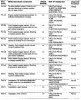
Lucas I4CU
Flash! Description
FCR code
13212 Throttle pot sensor (TPS) or TPS circuit
13213 Throttle pot sensor (TPS) or TPS circuit
13214 Coolant temperature sensor (CTS) or CTS circuit
13215 Throttle pot sensor (TPS) or TPS circuit
13221 Airflow sensor (AFS) or AFS circuit
13222 Idle air control
13223 Weak mixture
13224 Rich mixture
13225 Oxygen sensor (OS) or OS circuit
13231 Ignition signal
13233 Electronic control module (ECM) fault
13234 Vehicle speed sensor (VSS) or VSS circuit
13235 No “Drive” signal - automatic transmission or circuit
Motronic 2.10.2, 2.8.1
Flash! Description
FCR code
11 Secondary injection or circuit
12 No faults found in the ECM. Proceed with normal diagnostic methods
21 Airflow sensor (AFS) or AFS circuit
31 Air temperature sensor (ATS) or ATS circuit
41 Coolant temperature sensor (CTS) or CTS circuit
51 Throttle pot sensor (TPS) or TPS circuit
61 Oxygen sensor (OS) cylinder 1, 3, 5 or OS circuit
62 Oxygen sensor (OS) cylinder 2, 4, 6 or OS circuit
71 Oxygen sensor (OS) cylinder 1, 3, 5, rich or lean
72 Oxygen sensor (OS) cylinder 2, 4, 6, rich or lean
73 Oxygen sensor (OS) rich or lean
81 Evaporative emission canister purge valve or circuit
91 Electronic control module (ECM)
92 Electronic control module (ECM)
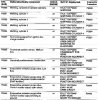
Saab Trionic
FCR Description
code
P0105 Manifold absolute pressure (MAP) sensor or MAP sensor circuit
P0106 Manifold absolute pressure (MAP) sensor or MAP sensor circuit, signaI low
P0107 Manifold absolute pressure (MAP) sensor or MAP sensor circuit, signal high
P0108 Manifold absolute pressure (MAP) sensor or MAP sensor circuit
P0110 Air temperature sensor (ATS) or ATS circuit
P0112 Air temperature sensor (ATS) or ATS circuit, signal low
P0113 Air temperature sensor (ATS) or ATS circuit, signal high
P0115 Coolant temperature sensor (CTS) or CTS circuit
P0117 Coolant temperature sensor (CTS) or CTS circuit, signal low
P0118 Coolant temperature sensor (CTS) or CIS circuit, signal high
P0120 Throttle pot sensor (TPS) or TPS circuit
P0121 Throttle pot sensor (TPS) or TPS circuit
P0122 Throttle pot sensor (TPS) or TPS circuit, signal low
P0123 Throttle pot sensor (TPS) or TPS circuit, signal high
P0130 Oxygen sensor (OS) or OS circuit
P0135 Oxygen sensor (OS) or OS circuit
P1130 Oxygen sensor (OS) or OS circuit, current high
P1135 Oxygen sensor (OS) or OS circuit, current low
P0170 Fuel/air mixture or circuit
P0171 Weak mixture
P0172 Rich mixture
P1322 Engine speed (RPM) sensor or circuit
P0325 Knock sensor (KS) or KS circuit
P0335 Engine speed (RPM) sensor or circuit
P0335 Crank angle sensor (CAS) or CAS circuit
P0443 Carbon filter solenoid valve (CFSV) or CFSV circuit
P1443 Carbon filter solenoid valve (CFSV) or CFSV circuit
P1444 Carbon filter solenoid valve (CFSV) or CFSV circuit, current high
P1445 Carbon filter solenoid valve (CFSV) or CFSV circuit, current low
P0500 Vehicle speed sensor (VSS) or VSS circuit
P0501 Vehicle speed sensor (VSS) or VSS circuit
P0502 Vehicle speed sensor (VSS) or VSS circuit, signal low
P0505 Idle speed control valve (ISCV) or ISCV circuit
P1500 Battery voltage
P0605 Electronic control module (ECM)
P1651 Electronic control module (ECM)
P1652 Electronic control module (ECM)
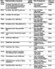
Bosch LH 2.4/2.4.1/2.4.2
(flash codes)
Flash Description
code
12111 Oxygen sensor (OS) fault (fuel air mixture on idling)
12112 Oxygen sensor (OS) fault (fuel air mixture engine at cruising speed)
12113 Idle speed control valve (ISCV) adaption fault, pulse ratio too low
12114 Idle speed control valve (ISCV) adaption fault, pulse ratio to high
12211 Battery voltage, less than 10 volts or greater than 16 volts
12212 Throttle switch (IS), idle contacts
12213 Throttle switch (IS), full-load contacts
12214 Temperature sensor signal faulty (below 90°C or above 160°C)
12221 No air mass meter signal
12222 Air conditioning system faulty
12223 Fuel air mixture lean, OS sensor shorting to earth
12224 Fuel air mixture rich, OS sensor shorting to battery voltage
12225 Oxygen sensor (OS) or OS heater fault
12232 Voltage supply to ECM pin 4 is less than 1 volt
12233 Fault in electronic control module (ECM) - read only memory (ROM)
12241 Mixture lean
12242 Hot-wire burn-off function faulty
12243 No signal from vehicle speed sensor
12244 No “Drive” signal (automatic transmission)
12245 Exhaust gas recirculation (EGR) function faulty
00000 No faults detected, or all fault codes have been transmitted
Bosch LH 2.4 ac&ator selection code table
Note: The actuators will actuate in the following sequence. Listen for an audible sound, or touch the component to determine whether it has been activated
Code Description
No display Fuel pump circuit
12411 Injector circuit
12412 Idle speed control valve (ISCV) circuit
12413 Carbon filter solenoid valve (CFSV) circuit
12421 Automatic transmission (auto) drive signal. The SD light ceases flashing when the gear lever is moved from “D” to “N”
12424 Throttle switch (IS), idle contacts. Slightly open the throttle. The SD light ceases flashing once the throttle moves away from the idle position
12431 Throttle switch (IS), full-load contacts. Fully open the throttle. The SD light ceases flashing as the throttle approaches the fully-open position
Bosch LH 2.4/2.4,2 and Saab Direct Ignition (FCR codes)
FCR code FCR code
(permanent) (intermittent) Description
11111 - Reply code for OK
42241 22241 High voltage (1991 -on)
42251 22251 Electronic control module (ECM) pin 4, signal low
42252 22252 Signal low, less than 10 volts
42291 22291 Battery voltage, less than 10 volts/greater than 16 volts
42440 22440 Oxygen sensor (OS) or OS circuit, rich mixture
42441 22441 Rich mixture, idling (1991-on)
42442 22442 Rich mixture, driving (1991-on)
42450 22450 Oxygen sensor (OS) or OS circuit, weak mixture
42451 22451 Weak mixture, idling (1991-on)
42452 22452 Weak mixture, driving (1991-on)
42460 22460 Oxygen sensor (OS) or OS circuit
42491 22491 Idling mixture incorrect
42492 22492 Driving mixture incorrect
44221 24221 Engine RPM signal absent (1991-on)
44261 24261 Vehicle speed sensor (VSS) or VSS circuit (1991-on)
44360 24360 Crank angle sensor (CAS) or CAS circuit
44460 24460 Engine load signal faulty
44660 24660 Pre-ignition fault (knocking or pinking)
44661 24461 Knock sensor (KS) or KS circuit
44662 24462 Combustion, synchronising fault
44671 24671 Pre-ignition signal over 20 seconds
45641 25641 Mass airflow (MAF) sensor or MAF sensor circuit, signal high
45651 25651 Mass airflow (MAF) sensor or MAF sensor circuit, signal low
45691 25691 Mass Airflow (MAF) sensor or MAF sensor circuit
45723 25723 “Drive” signal (automatic transmission)
45771 25771 Throttle pot sensor (IPS) signal or IPS circuit
45772 25772 Throttle pot sensor (IPS) signal or TPS circuit
46221 26221 Coolant temperature sensor (CTS) or CTS circuit, signal low
46271 26271 Coolant temperature sensor (CTS) or CTS circuit, signal high
46391 26391 Exhaust gas recirculation (EGR) system or EGR circuit
58121 38121 Mass airflow (MAF) sensor or MAF sensor circuit, bum-off absent
58321 38321 Air conditioning valve function or circuit
58322 38322 Evaporative loss control device (ELCD) valve function or circuit
58371 38371 Injector or injector circuit
58372 38372 Evaporative loss control device (ELCD) valve or circuit
58382 38382 Evaporative loss control device (ELCD) valve short-circuit (1991-on)
60000 - Internal monitoring
60001 - Read only memory (ROM) fault
60002 - Random access memory (RAM) fault
67192 - Electronic control module (ECM), read only memory (ROM)
Trionic flash codes
flashes component correspondingisat codes
2 Manifold absolute pressure sensor p0105, p0106, p0107, p0108
3 Intake air temp sensor p0110, p0112, p0113
4 coolant temp sensor p0115, p0117, p0118
5 throttle position sensor p0120, p0121, p0122, p0123
6 oxygen sensor p0130
7 Air fuel mixture p0170, p0171, p0172
8 Evap valve (ELCD) p0443, p1443, p1444, p1445
Grüße Balze
 ).
).